


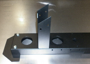
P
E
H
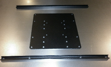
L1
A
D
C
F
B1
I
J
G
K
N
O

Q1
Q2
R
M
Back to main page Here

I2
T
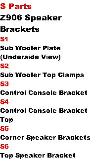
S2
S1
S6
S5
S5
S4

5.
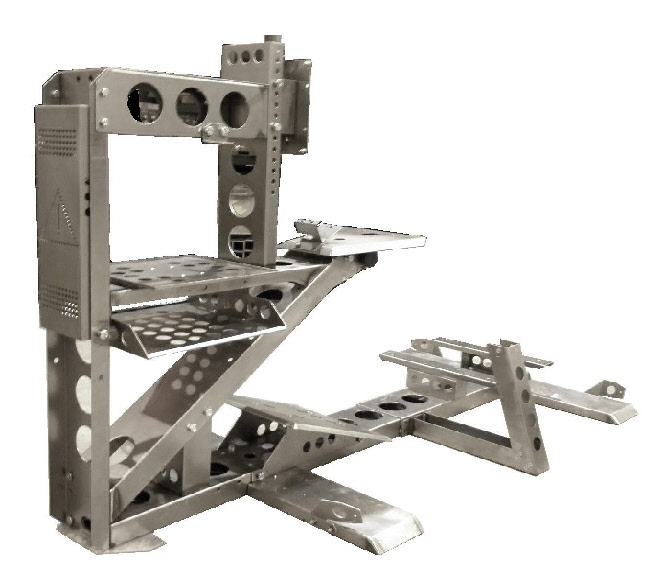
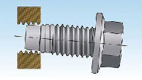
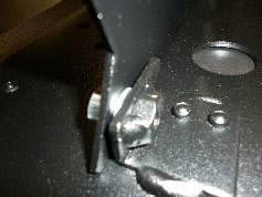
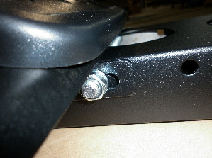
Fit the Screen Mount Lower H Beam (Part F) to the Main Front V Beam (Part H) with 4 off M10 x20mm bolts, nuts and washers.
Its best to leave these bolts loose while fitting the other side of the H Beam to the Wheel Column.
Use 2 off M10 x20mm bolts and washers to connect the other side of the H Beam to the Wheel Column. (The Wheel Column has two sets of threaded bushes - use the top ones)
Fit the Screen Mount Lower H Beam (Part F) to the Main Front V Beam (Part H) with 4 off M10 x20mm bolts, nuts and washers.
Its best to leave these bolts loose while fitting the other side of the H Beam to the Wheel Column.
Use 2 off M10 x20mm bolts and washers to connect the other side of the H Beam to the Wheel Column. (The Wheel Column has two sets of threaded bushes -
Ignore the 2 lower threaded holes - these are for a different screen mount which may be available later.

6.
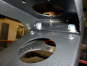
Next fit the Main Front Foot (Part B1) to the Front Base (Part A) with 2 off M10 x55mm bolts and washers.
Make sure the speaker mounting holes are to the Front of the Cockpit.
Its not a bad idea to fit the Speaker Brackets (Part S5) to the Front Foot before fitting to the Base...You may as well fit the Speaker Brackets to the Rear Foot (Part B2) now as well.
B2
B1
B2
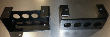
Fitting the Speaker Brackets.
The Front “Left Hand” Speaker Bracket is Shown in Pictures.
(The Rear “Right Hand” would look the same)
Use 2 off M8 x20mm bolts, nuts and washers for each Bracket.
Brackets tilt forward from the base then inward.
The Front “Left Hand” Speaker Bracket is Shown in Pictures.
(The Rear “Right Hand” would look the same)
Use 2 off M8 x20mm bolts, nuts and washers for each Bracket.
Brackets tilt forward from the base then inward.
TOP DOWN VIEW
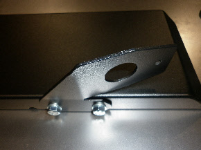
The Rear Foot is identified by small holes here.
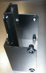
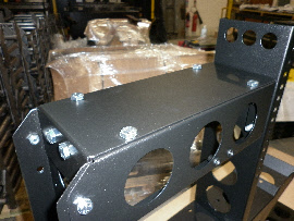
7.
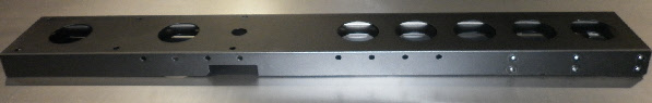
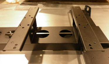
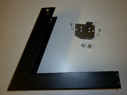
Next fit the Screen Mount Vertical Beam (Part G) to Horizontal Beam (Part F) with 2 off M10 x20mm bolts, nuts and washers.
The hollow section goes to the back of the cockpit so the Screen Mount U Bracket (Part J) can bolt inside it.
8.
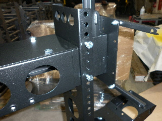
Then fit both the “Left” and “Right” hand Front Upper Horizontal Side Parts and Spacers (Parts I1 and I2) to the Part G using 4 off M10 x40mm bolts (do not use washers here - tight clearance on Part J means the bolts must not stick out further than necessary)
- and to part H using 2 off M8 x20mm and 2 off M10 x20mm bolts, nuts and washers.
Next fit the Screen Mount Vertical Beam (Part G) to Horizontal Beam (Part F) with 2 off M10 x20mm bolts, nuts and washers.
The hollow section goes to the back of the cockpit so the Screen Mount U Bracket (Part J) can bolt inside it.
8.
Then fit both the “Left” and “Right” hand Front Upper Horizontal Side Parts and Spacers (Parts I1 and I2) to the Part G using 4 off M10 x40mm bolts (do not use washers here -
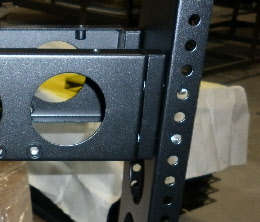
Part I1
Part I2 (Spacer) *
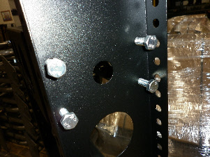
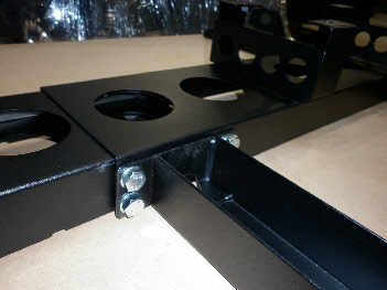
View of the 4 off M10 x40mm bolts from the inside of Part G.
These bolts go through the spacers and into the threaded holes in the Upper Horizontal Side Parts
These bolts go through the spacers and into the threaded holes in the Upper Horizontal Side Parts
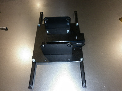
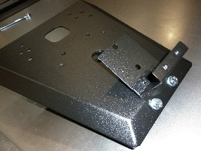
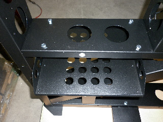
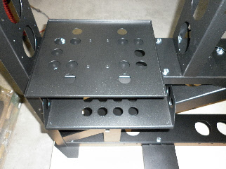
9.
Now fit the Top Cover (Part K) using 6 off M10 x12mm bolts and washers.
Now fit the Top Cover (Part K) using 6 off M10 x12mm bolts and washers.
Assembling the Screen Mount Parts.
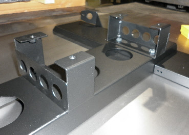
10
Fit the Screen Mount U Bracket (Part J) to the 200mm Plate (Part L1) using 4 off M6 x16mm bolts and washers.
If the TV requires a 400mm x 200mm mounting then fit the 400mm Crossbars as well.
Fit the Screen Mount U Bracket (Part J) to the 200mm Plate (Part L1) using 4 off M6 x16mm bolts and washers.
If the TV requires a 400mm x 200mm mounting then fit the 400mm Crossbars as well.
11
Now the Screen Mount Assembly can be fitted using 4 off M10 x20mm bolts and washers.
Now the Screen Mount Assembly can be fitted using 4 off M10 x20mm bolts and washers.
14
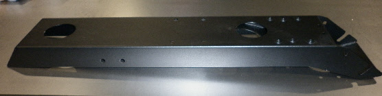
Fit the Rear Foot (Part B2) to the Rear Base (Part M) using 2 off M10 x 60mm bolts and washers.
15
Now fit the Seat Brackets (Part N) to the Rear Base using 2 off M10 x20mm bolts and washers.
Fit the Rear Foot (Part B2) to the Rear Base (Part M) using 2 off M10 x 60mm bolts and washers.
15
Now fit the Seat Brackets (Part N) to the Rear Base using 2 off M10 x20mm bolts and washers.
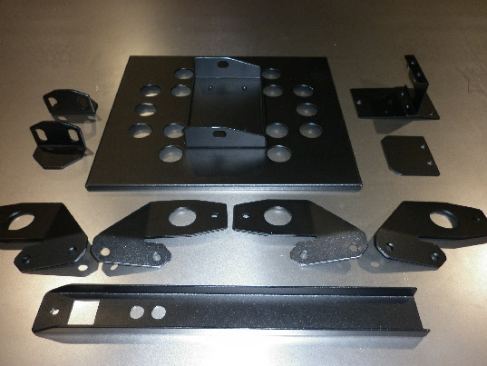
Moving on to the Rear Base Assembly.
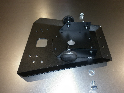
12
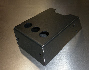
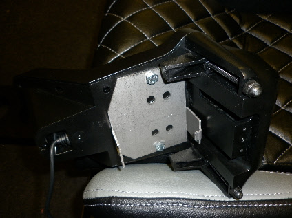
Fit the Z906 Control Console Mount (Part S3) to Wheel Table (Part P) using 2 off M8 x 20mm bolts, nuts and washers.
13
Now fit the Wheel Table to the Wheel Column with 2 off M10 x20mm bolts and washers. And 2 off M10 Handwheels
Fit the Z906 Control Console Mount (Part S3) to Wheel Table (Part P) using 2 off M8 x 20mm bolts, nuts and washers.
13
Now fit the Wheel Table to the Wheel Column with 2 off M10 x20mm bolts and washers. And 2 off M10 Handwheels
16
Fit the Seat Bracket Crossbars (Part O) using 2 off M10 x 20 mm bolts and washers.
How the Cross Bars fit on the Brackets depends on the type of Seat being fitted.
From September 2017
An updated diagram will be included with the cockpit.
Fit the Seat Bracket Crossbars (Part O) using 2 off M10 x 20 mm bolts and washers.
How the Cross Bars fit on the Brackets depends on the type of Seat being fitted.
From September 2017
An updated diagram will be included with the cockpit.


B
A
U
17
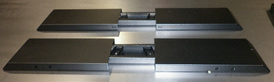
The Front and Rear sections can now be joined together using 8 off M10 x20mm bolts and washers.
If fitted, the Gear Shift (Part U) also fits at the join point using the same bolts.
The Front and Rear sections can now be joined together using 8 off M10 x20mm bolts and washers.
If fitted, the Gear Shift (Part U) also fits at the join point using the same bolts.
Picture shows Gear Shift fitted with 4x M10 bolts.
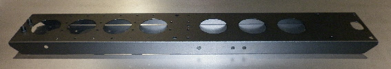
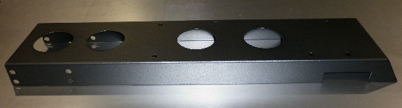
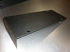
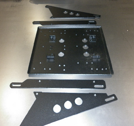
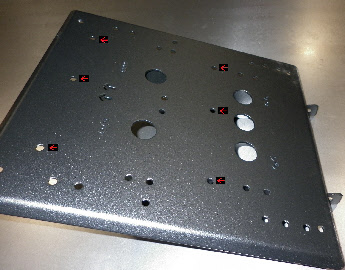
Pedal Plate Assembly. / Fixing Pedals.
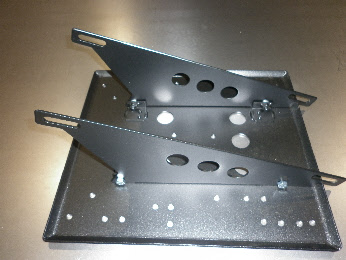
Use an M8 washer Here. (4 places)
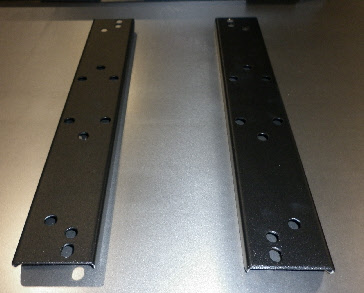
18
Fit the Pedal Plate Sides (Parts Q2 using 4 off M8 x20mm bolts and washers.
As of August 2017. Also use a washer between the pedal plate and the bracket as a spacer.
See picture below.
Fit the Pedal Plate Sides (Parts Q2 using 4 off M8 x20mm bolts and washers.
As of August 2017. Also use a washer between the pedal plate and the bracket as a spacer.
See picture below.
The Red Arrows point out the fixing holes for the Logitech G29 or G920 Pedals.
(Holes are also included for several Thrustmaster and Fanatec Pedals.)
Fit the Logitech Pedals with 6 off M6 x 20mm bolts and washers.
(Holes are also included for several Thrustmaster and Fanatec Pedals.)
Fit the Logitech Pedals with 6 off M6 x 20mm bolts and washers.
Next fit the pedals to the Pedal Plate
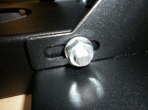
The Pedal Plate is now ready to be fitted to the Front Base using 4 off M10 x20mm bolts . Its best to leave this for now until the Seat and Wheel have been installed so you can choose which set of holes to use for the best position of the Pedals.
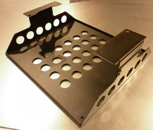
Pedal Base Side Mounting Holes
Console and Speaker Sub Woofer Mountings.
19
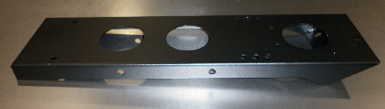
Fit the Console Tray (Part R) to the Screen Mount Lower Horizontal Beam (Part F) using 4 off M6 x20mm bolts, nuts and washers.
Fit the Console Tray (Part R) to the Screen Mount Lower Horizontal Beam (Part F) using 4 off M6 x20mm bolts, nuts and washers.
20
Fit the Sub Woofer Plate (Part S1) to the Screen Mount Lower Horizontal Beam (Part F) using 2 off M10 x20mm bolts, nuts and washers.
After the Sub Woofer is installed The TOP CLAMPS (Parts S2) can be fitted each using 2 off M10 x20mm bolts and washers.
Fit the Sub Woofer Plate (Part S1) to the Screen Mount Lower Horizontal Beam (Part F) using 2 off M10 x20mm bolts, nuts and washers.
After the Sub Woofer is installed The TOP CLAMPS (Parts S2) can be fitted each using 2 off M10 x20mm bolts and washers.
Fitting the Seat (Autostyle RS6 type seats)
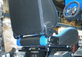
Use 4 off M8x 20mm allen bolts, nuts and washers to mount the seat to the the Seat Bracket Crossbars
Fitting the G27/G29 Logitech Wheel
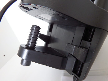
Fit the Wheel using 2 off M6 x20mm bolts and washers.
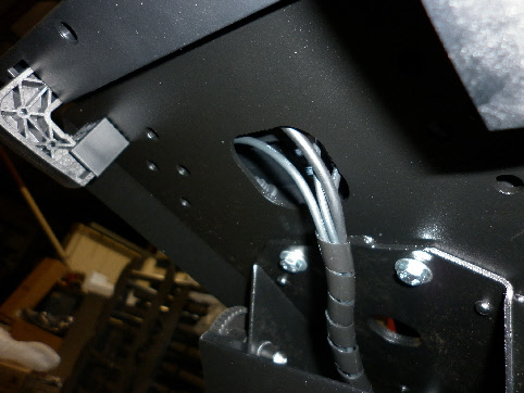
Remember to first thread the wires through the hole before attaching the wheel.
Remember to first thread the wires through the hole before attaching the wheel.
Wheel Table underside view

* for Logitech z906 Speakers Only
Fitting the G27/G29 Gear Shift.
First remove the clamp from the bottom of the G27/G29 Shifter.
There are 4 Phillips screws (2 are deep inside the plastic moulding so a long screw driver is needed)
There are 4 Phillips screws (2 are deep inside the plastic moulding so a long screw driver is needed)

Small Hook
Fit the Gear Shift Top Bracket (Part U2) to the shifter using 2 off M6 x 16mm bolts and washers.
The small hook part fits to the rear of the shifter as shown in the picture.
The small hook part fits to the rear of the shifter as shown in the picture.
Slot for ‘hook’ on Part U2
If fitting a Screen with 200x100 or 200x200 hole centres you may need to use the 4x 6mm plastic spacers between the screen mount plate and TV mounting holes.
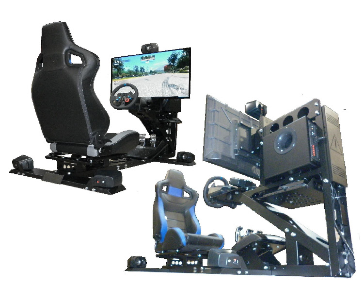
Assuming you have bought just the cockpit frame and seat this is a full list of items needed to complete the simulator.
1. A Steering Wheel and Pedal Set. (See compatible wheel and pedals list below)
2. A Wall Mountable 32” to 50” TV with HDMI Input. (SeeTV bracket mounting size list below)
3. A Sony PS3, PS4 or XBOX ONE Game Console. (You could also use a PC, but I’m keeping things simple for this guide! - I may tackle this aspect later, but if you are thinking for using a PC for this you may already know more than I do about the best current PC set up!)
4. (Optional) Logitech Z906 Speaker Set. + An optical digital audio cable to connect the speakers.
5. A 4 Gang Mains Extension Lead (To power the TV, Console, Wheel/Pedals and Speakers)
Everything else needed such as wiring and connection cables either comes with the above items or will come with the cockpit frame.
Also included with the cockpit frame are the bolts needed to mount the TV, speakers and most popular steering wheels and pedals.
1. A Steering Wheel and Pedal Set. (See compatible wheel and pedals list below)
2. A Wall Mountable 32” to 50” TV with HDMI Input. (SeeTV bracket mounting size list below)
3. A Sony PS3, PS4 or XBOX ONE Game Console. (You could also use a PC, but I’m keeping things simple for this guide! -
4. (Optional) Logitech Z906 Speaker Set. + An optical digital audio cable to connect the speakers.
5. A 4 Gang Mains Extension Lead (To power the TV, Console, Wheel/Pedals and Speakers)
Everything else needed such as wiring and connection cables either comes with the above items or will come with the cockpit frame.
Also included with the cockpit frame are the bolts needed to mount the TV, speakers and most popular steering wheels and pedals.
Screen Mountings.
Standard VESA TV hole pattern sizes included:
200 x 100, 200 x 200 and 200 x 400 (a 400 x 400 bracket can be added on request)
Almost all new TV’s now have wall mounting holes on the back in one of the above sizes.
Wheels and Pedals.
The Cobra v3 has mounting holes for the following units.
Logitech G27, G29 and G920
Thrustmaster T150, T300, TMX, T500 and TS PC Racer.
(Optional) Gear Shift.
Logitech G27/G29 and Thrustmaster TH8A
(Optional) Speakers.
Speaker mounting are designed for the Logitech Z906 surround sound speaker set.
As of June 2017 use standard 20mm bolts and washers (2 from each side) instead of the long bolts and nuts shown in the pictures below.
* Spacer no longer needed as of July 2019
Use M10 x20 bolts instead of M10 x40
Use M10 x20 bolts instead of M10 x40
Remove this part


Aug 2019
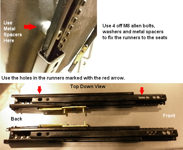
Spacers no longer come supplied with the seat sliders.
Please use M10 nuts as spacers instead.
Spacers no longer come supplied with the seat sliders.
Please use M10 nuts as spacers instead.
Use these parts for angled pedals
Use these parts for flat pedals
From May 2019
USE ALLEN BOLTS HERE FOR EASIER ACCESS.
USE ALLEN BOLTS HERE FOR EASIER ACCESS.

x2
November 2020:
Pedal Plate Sides are now made double thickness for extra strength.
Ensure the small rivet protrusions go on the OUTSIDE face so smooth faces go on the inside.
Pedal Plate Sides are now made double thickness for extra strength.
Ensure the small rivet protrusions go on the OUTSIDE face so smooth faces go on the inside.


Hand Wheels now replaced with Allen Bolts.
(Allen Key Supplied)
(Allen Key Supplied)